Clamper, Clamper Circuit, Diode Clamper Circuit, Clamper Electronics, Clamper Circuit Analysis
What is Clamper?
Clamper circuit
fixes one extremity of a wave form to a certain voltage level regardless of
changes in the input wave form. Thus in the clamper circuit the input and
output signals have the same shape but different dc levels.
POSITIVE
CLAMPER
Drawing output of
Circuit Below:
CLAMPER 1:
In
the first +ve cycle of the diode D is reverse bias.
During the first –ve cycle of the input the
diode D is forward bias. Current in the circuit will flow from point B-D-C-A.
This will charge capacitor C in the shown polarity to the peak input voltage
(Vm). Applying KVL in –ve cycle.
Capacitor
Voltage Vc is Vm.
Now Applying KVL in +ve cycle.
The
circuit has a output in which the waveform is shifting up thus it is called
Positive Clamper.
Drawing output of
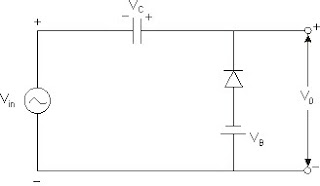
Circuit Below (Biased Clamper):
CLAMPER 2:
During +ve Cycle, Apply KVL
Drawing output of Circuit Below (Biased Clamper):
CLAMPER 3:
During –ve cycle
During +ve cycle
NEGATIVE CLAMPER
If we turn the diode, the polarity of capacitor voltage reverses and the circuit becomes negative Clamper.
Drawing output of Circuit Below:
CLAMPER 4:
Drawing output of Circuit Below (Biased Clamper):
CLAMPER 5:
During +ve cycle
Drawing output of Circuit Below (Biased Clamper):
CLAMPER 6:
To calculate Vc
To Calculate Vo


No comments:
Post a Comment